flat assembler
Message board for the users of flat assembler.
Index
> Tutorials and Examples > Box3D shared and static support for fasm2:Goto page 1, 2 Next |
| Author |
|
|
bitRAKE 02 Jul 2026, 01:55
Box3D v0.1.0 was released, and I wanted to play with it. So, here is fasm2 support and an example. The coding style follows the OpenGL example in fasm2 - no fancy stuff. There are some notes on using the library in relation to assembly; as well as instruction on how to build the libraries from the source repo. (Okay not to trust my binaries, or maybe you want double precision.)
Who doesn't want to blow up a digital pyramid? _________________ ¯\(°_o)/¯ AI may [not] have aided with the above reply. |
|||
|
|
Roman 25 Jul 2026, 17:56
Respect ! Cool demos !
How you write box3D structs for fasm? Using some tools(notepad++ and python) or all write hands ? |
|||
|
|
bitRAKE 25 Jul 2026, 21:42
Roman wrote: How you write box3D structs for fasm? Using some tools(notepad++ and python) or all write hands ? _________________ ¯\(°_o)/¯ AI may [not] have aided with the above reply. |
|||
|
|
Roman 26 Jul 2026, 06:31
I am looking how did get all functions from dll file.
And create text all dll functions. I found this fasm variant https://github.com/RootDmytro/dll2inc I do this example 32bits. In run.bat write your dll and get all functions import names ! Enjoy ! I tested only 32bits dll. Work fine.
|
|||||||||||
|
|
bitRAKE 26 Jul 2026, 17:24
I like "dumpbin /EXPORTS" if I'm automating.
|
|||
|
|
macomics 26 Jul 2026, 19:10
Roman wrote: I am looking how did get all functions from dll file. |
|||
|
|
Roman 26 Jul 2026, 20:33
bitRAKE you implement b3MakeMatrixFromQuat for fasm ?
b3MakeMatrixFromQuat not exist in box3D.dll. I looking fast avx variant convert quaternion to matrix3x3. |
|||
|
|
bitRAKE 27 Jul 2026, 03:22
Thanks for the bug report.
Code: ; b3MakeMatrixFromQuat dst_matrix_addr,q_addr ; Destination must not overlap q. ; The 36-byte result is emitted as two 16-byte stores and one scalar store. ; Clobbers: XMM0-XMM3, EAX macro b3MakeMatrixFromQuat dst*,q* ; xmm0 = [x,y,z,w]. A b3Quat is exactly 16 bytes, so this load is bounded. movups xmm0,xword [q] ; [yy,xy,xz,xy] +/- [zz,zw,yw,zw] pshufd xmm1,xmm0,01h ; [y,x,x,x] pshufd xmm2,xmm0,65h ; [y,y,z,y] mulps xmm1,xmm2 pshufd xmm2,xmm0,09Ah ; [z,z,y,z] pshufd xmm3,xmm0,0FEh ; [z,w,w,w] mulps xmm2,xmm3 pcmpeqd xmm3,xmm3 pslld xmm3,31 pslldq xmm3,8 ; negate lanes 2 and 3 xorps xmm2,xmm3 addps xmm1,xmm2 addps xmm1,xmm1 psrldq xmm3,12 ; negate diagonal lane 0 xorps xmm1,xmm3 mov eax,3F800000h movd xmm3,eax addps xmm1,xmm3 movups xword [dst],xmm1 ; cx.xyz, cy.x ; [xx,yz,xz,yz] +/- [zz,xw,yw,xw] pshufd xmm1,xmm0,44h ; [x,y,x,y] pshufd xmm2,xmm0,0A8h ; [x,z,z,z] mulps xmm1,xmm2 pshufd xmm2,xmm0,12h ; [z,x,y,x] pshufd xmm3,xmm0,0FEh ; [z,w,w,w] mulps xmm2,xmm3 pcmpeqd xmm3,xmm3 pslld xmm3,31 pslldq xmm3,12 ; negate lane 3 xorps xmm2,xmm3 addps xmm1,xmm2 addps xmm1,xmm1 psrldq xmm3,12 ; negate diagonal lane 0 xorps xmm1,xmm3 movd xmm3,eax addps xmm1,xmm3 movups xword [dst+16],xmm1 ; cy.yz, cz.xy ; cz.z = 1 - 2*(xx+yy) movaps xmm1,xmm0 mulss xmm1,xmm0 pshufd xmm2,xmm0,55h ; [y,y,y,y] mulss xmm2,xmm2 addss xmm1,xmm2 addss xmm1,xmm1 movd xmm2,eax subss xmm2,xmm1 movss dword [dst+32],xmm2 end macro |
|||
|
|
Roman 27 Jul 2026, 03:41
Last right ?
Quote:
Why ? Why not movups xword [dst+32],xmm2 ? Origin function Box3D Code: B3_FORCE_INLINE b3Matrix3 b3MakeMatrixFromQuat( b3Quat q ) { float xx = q.v.x * q.v.x; float yy = q.v.y * q.v.y; float zz = q.v.z * q.v.z; float xy = q.v.x * q.v.y; float xz = q.v.x * q.v.z; float xw = q.v.x * q.s; float yz = q.v.y * q.v.z; float yw = q.v.y * q.s; float zw = q.v.z * q.s; ;return 9 floats return ( b3Matrix3 ){ { 1.0f - 2.0f * ( yy + zz ), 2.0f * ( xy + zw ), 2.0f * ( xz - yw ) }, { 2.0f * ( xy - zw ), 1.0f - 2.0f * ( xx + zz ), 2.0f * ( yz + xw ) }, { 2.0f * ( xz + yw ), 2.0f * ( yz - xw ), 1.0f - 2.0f * ( xx + yy ) }, }; } |
|||
|
|
Roman 27 Jul 2026, 07:01
Thanks BitRake. Now worked perfect ! I tested in directx11.
My variant for matrix4x4 Code: SSE_quat2mat4: dst@rreg equ edx ; xmm0 = [x,y,z,w]. A b3Quat is exactly 16 bytes, so this load is bounded. movups xmm0,xword [eax] ; [yy,xy,xz,xy] +/- [zz,zw,yw,zw] pshufd xmm1,xmm0,01h ; [y,x,x,x] pshufd xmm2,xmm0,65h ; [y,y,z,y] mulps xmm1,xmm2 pshufd xmm2,xmm0,09Ah ; [z,z,y,z] pshufd xmm3,xmm0,0FEh ; [z,w,w,w] mulps xmm2,xmm3 pcmpeqd xmm3,xmm3 pslld xmm3,31 pslldq xmm3,8 ; negate lanes 2 and 3 xorps xmm2,xmm3 addps xmm1,xmm2 addps xmm1,xmm1 psrldq xmm3,12 ; negate diagonal lane 0 xorps xmm1,xmm3 mov eax,3F800000h movd xmm3,eax addps xmm1,xmm3 movups xword [dst@rreg],xmm1 ; cx.xyz, cy.x ;convert mat4x4 mov ecx,[dst@rreg+12] mov dword [dst@rreg+12],0 mov [dst@rreg+16],ecx ; [xx,yz,xz,yz] +/- [zz,xw,yw,xw] pshufd xmm1,xmm0,44h ; [x,y,x,y] pshufd xmm2,xmm0,0A8h ; [x,z,z,z] mulps xmm1,xmm2 pshufd xmm2,xmm0,12h ; [z,x,y,x] pshufd xmm3,xmm0,0FEh ; [z,w,w,w] mulps xmm2,xmm3 pcmpeqd xmm3,xmm3 pslld xmm3,31 pslldq xmm3,12 ; negate lane 3 xorps xmm2,xmm3 addps xmm1,xmm2 addps xmm1,xmm1 psrldq xmm3,12 ; negate diagonal lane 0 xorps xmm1,xmm3 movd xmm3,eax addps xmm1,xmm3 ;movups xword [dst@rreg+16],xmm1 ; cy.yz, cz.xy ;convert mat4x4 movups xword [dst@rreg+20],xmm1 mov ecx,[dst@rreg+20+12-4] mov ebx,[dst@rreg+20+12] mov [dst@rreg+32],ecx mov [dst@rreg+36],ebx mov dword [dst@rreg+20+12-4],0 ; cz.z = 1 - 2*(xx+yy) movaps xmm1,xmm0 mulss xmm1,xmm0 pshufd xmm2,xmm0,55h ; [y,y,y,y] mulss xmm2,xmm2 addss xmm1,xmm2 addss xmm1,xmm1 movd xmm2,eax subss xmm2,xmm1 movss dword [dst@rreg+32+8],xmm2 ret |
|||
|
|
Roman 29 Jul 2026, 12:01
BitRake how did you get vertices from BoxHull ?
I mean show box in opengl render the same size as BoxHull created Box3D |
|||
|
|
bitRAKE 29 Jul 2026, 16:38
The benchmark does not extract render vertices from `b3BoxHull`. It uses a shared unit-cube OpenGL mesh and makes it match the physics hull through per-instance scale and transform data.
The flow is: 1. One render mesh is created with corners from `-1` to `+1` on each axis in (benchmark.asm:127). 2. Physics boxes are created with half-extents: Code: b3MakeBoxHull cubeHull, 0.5, 0.5, 0.5 3. Each render instance stores: position.xyz | quaternion.xyzw | halfExtents.xyz | color.rgb The OpenGL attribute layout is configured in (benchmark.asm:366). 4. Initial position and rotation come from `b3BodyDef`. The benchmark generates the grid position and random rotation, then copies those values into the corresponding render-instance record before creating the body. The instance index is stored in `bdef.userData`. See (benchmark.asm:672) and (benchmark.asm:724). 5. After each simulation step, `b3World_GetBodyEvents` returns only the bodies that moved. Each event contains: Code: userData transform.p transform.q `userData` selects the instance slot, and the new position/quaternion replace the first 28 bytes of that record. The half-extents and color remain unchanged. See (benchmark.asm:403). 6. The vertex shader constructs the final world-space vertex: Code: world = bodyPosition + rotate(bodyQuaternion, unitCubeVertex * halfExtents); That is implemented directly in (benchmark_vs.glsl:15). So the box does not change size during simulation. Box3D is moving and rotating a rigid hull; only its body transform changes. For the benchmark cube: Code: unit render vertex: (-1 .. +1) half extents: (0.5, 0.5, 0.5) local rendered box: (-0.5 .. +0.5) physics hull: (-0.5 .. +0.5) The ground uses exactly the same unit mesh, but its instance half-extents are `(100, 0.5, 100)`, matching its `b3MakeBoxHull` arguments. Its center is `(0, -0.5, 0)`, placing the upper face at `y = 0`. If you genuinely want the vertices from `b3BoxHull`, the position data is not in `boxVertices`; those are topology records. Use the hull points: Code: b3BoxHull box = b3MakeBoxHull(hx, hy, hz); const b3HullData* hull = &box.base; const b3Vec3* points = b3GetHullPoints(hull); for (int i = 0; i < hull->vertexCount; ++i) { b3Vec3 localVertex = points[i]; } `b3GetHullPoints` resolves the embedded point array in (collision.h:145). To build triangles for an arbitrary hull, traverse its faces and half-edges; the repository renderer demonstrates that in (box3d\samples\gfx\debug_shapes.c:296). Transform each resulting local vertex using the body’s current position and quaternion. _________________ ¯\(°_o)/¯ AI may [not] have aided with the above reply. |
|||
|
|
Roman 29 Jul 2026, 17:00
Hm.
In b3HullData exist vertexOffset. I thinked b3CreateCylinder created vertices and indices. And my idea was get vertices and indices and create Directx 11 mesh for render. I looking and not see vertex data and indices data. Only points Code: b3HullData* b3CreateCylinder( float height, float radius, float yOffset, int sides ) { B3_ASSERT( height > 0.0f ); B3_ASSERT( radius > 0.0f ); B3_ASSERT( 3 <= sides && sides <= 32 ); int pointCount = 2 * sides; b3Vec3* points = (b3Vec3*)b3Alloc( pointCount * sizeof( b3Vec3 ) ); B3_ASSERT( points != NULL ); float alpha = 0.0f; float deltaAlpha = 2.0f * B3_PI / sides; for ( int index = 0; index < sides; ++index ) { float sinAlpha = b3Sin( alpha ); float cosAlpha = b3Cos( alpha ); points[2 * index + 0] = (b3Vec3){ radius * cosAlpha, yOffset, radius * sinAlpha }; points[2 * index + 1] = (b3Vec3){ radius * cosAlpha, yOffset + height, radius * sinAlpha }; alpha += deltaAlpha; } b3HullData* hull = b3CreateHull( points, pointCount, pointCount ); B3_ASSERT( hull->vertexCount == pointCount ); B3_ASSERT( hull->edgeCount == 6 * sides ); B3_ASSERT( hull->faceCount == sides + 2 ); b3Free( points, pointCount * sizeof( b3Vec3 ) ); return hull; } |
|||
|
|
Roman 30 Jul 2026, 06:14
For my cylinder (height=3.5, radius=5, yOffset = 0 , sides=6) b3CreateCylinder created 12 points.
How i understood 6 points top cylinder and 6 points bottom cylinder. But i get points shuffled !
How generated triangles indices for cylinder ? Last edited by Roman on 30 Jul 2026, 08:13; edited 3 times in total |
|||
|
|
bitRAKE 30 Jul 2026, 06:57
You can make triangles or quads. For triangles, it's just two points from the top and one point from the bottom; then one point from the top and two points from the bottom -- all the way around the circles.
_________________ ¯\(°_o)/¯ AI may [not] have aided with the above reply. |
|||
|
|
Roman 30 Jul 2026, 07:56
I found Frank Luna cylinder.
http://richardssoftware.net/Home/Post/7 Code: void GeometryGenerator::CreateCylinder(float bottomRadius, float topRadius, float height, UINT sliceCount, UINT stackCount, MeshData& meshData) { meshData.Vertices.clear(); meshData.Indices.clear(); // // Build Stacks. // float stackHeight = height / stackCount; // Amount to increment radius as we move up each stack // level from bottom to top. float radiusStep = (topRadius - bottomRadius) / stackCount; UINT ringCount = stackCount+1; // Compute vertices for each stack ring starting at // the bottom and moving up. for(UINT i = 0; i < ringCount; ++i) { float y = -0.5f*height + i*stackHeight; float r = bottomRadius + i*radiusStep; // vertices of ring float dTheta = 2.0f*XM_PI/sliceCount; for(UINT j = 0; j <= sliceCount; ++j) { Vertex vertex; float c = cosf(j*dTheta); float s = sinf(j*dTheta); vertex.Position = XMFLOAT3(r*c, y, r*s); vertex.TexC.x = (float)j/sliceCount; vertex.TexC.y = 1.0f - (float)i/stackCount; // Cylinder can be parameterized as follows, where we // introduce v parameter that goes in the same direction // as the v tex-coord so that the bitangent goes in the // same direction as the v tex-coord. // Let r0 be the bottom radius and let r1 be the // top radius. // y(v) = h - hv for v in [0,1]. // r(v) = r1 + (r0-r1)v // // x(t, v) = r(v)*cos(t) // y(t, v) = h - hv // z(t, v) = r(v)*sin(t) // // dx/dt = -r(v)*sin(t) // dy/dt = 0 // dz/dt = +r(v)*cos(t) // // dx/dv = (r0-r1)*cos(t) // dy/dv = -h // dz/dv = (r0-r1)*sin(t) // TangentU us unit length. vertex.TangentU = XMFLOAT3(-s, 0.0f, c); float dr = bottomRadius-topRadius; XMFLOAT3 bitangent(dr*c, -height, dr*s); XMVECTOR T = XMLoadFloat3(&vertex.TangentU); XMVECTOR B = XMLoadFloat3(&bitangent); XMVECTOR N = XMVector3Normalize(XMVector3Cross(T, B)); XMStoreFloat3(&vertex.Normal, N); meshData.Vertices.push_back(vertex); } } // Add one because we duplicate the first and last vertex per ring // since the texture coordinates are different. UINT ringVertexCount = sliceCount+1; // Compute indices for each stack. for(UINT i = 0; i < stackCount; ++i) { for(UINT j = 0; j < sliceCount; ++j) { meshData.Indices.push_back(i*ringVertexCount + j); meshData.Indices.push_back((i+1)*ringVertexCount + j); meshData.Indices.push_back((i+1)*ringVertexCount + j+1); meshData.Indices.push_back(i*ringVertexCount + j); meshData.Indices.push_back((i+1)*ringVertexCount + j+1); meshData.Indices.push_back(i*ringVertexCount + j+1); } } BuildCylinderTopCap(bottomRadius, topRadius, height, sliceCount, stackCount, meshData); BuildCylinderBottomCap(bottomRadius, topRadius, height, sliceCount, stackCount, meshData); } void GeometryGenerator::BuildCylinderTopCap(float bottomRadius, float topRadius, float height, UINT sliceCount, UINT stackCount, MeshData& meshData) { UINT baseIndex = (UINT)meshData.Vertices.size(); float y = 0.5f*height; float dTheta = 2.0f*XM_PI/sliceCount; // Duplicate cap ring vertices because the texture coordinates // and normals differ. for(UINT i = 0; i <= sliceCount; ++i) { float x = topRadius*cosf(i*dTheta); float z = topRadius*sinf(i*dTheta); // Scale down by the height to try and make top cap // texture coord area proportional to base. float u = x/height + 0.5f; float v = z/height + 0.5f; meshData.Vertices.push_back( Vertex(x, y, z, 0.0f, 1.0f, 0.0f, 1.0f, 0.0f, 0.0f, u, v)); } // Cap center vertex. meshData.Vertices.push_back( Vertex(0.0f, y, 0.0f, 0.0f, 1.0f, 0.0f, 1.0f, 0.0f, 0.0f, 0.5f, 0.5f)); // Index of center vertex. UINT centerIndex = (UINT)meshData.Vertices.size()-1; for(UINT i = 0; i < sliceCount; ++i) { meshData.Indices.push_back(centerIndex); meshData.Indices.push_back(baseIndex + i+1); meshData.Indices.push_back(baseIndex + i); } } Last edited by Roman on 31 Jul 2026, 07:57; edited 1 time in total |
|||
|
|
bitRAKE 30 Jul 2026, 08:18
Here's a parametric shape generator. The AI was too extra: 10 base shapes, 7 exporters, 3D display, normals/UV/indexing machinery -- I didn't ask for all that.
_________________ ¯\(°_o)/¯ AI may [not] have aided with the above reply. |
|||||||||||
|
|
Roman 30 Jul 2026, 17:35
cool , but I writed my fasm code.
Code: myVrtx_Stride = 32 ;my mesh have pos.xyz,TextureUV.xy,Normals.xyz = 32 bytes one vertex macro msseSin t { movss [FourRadians],xmm0 addss xmm0,[pfl0@@_5] movss [FourRadians+4],xmm0 ;cos call sse@Sin } ;u = x/height + 0.5f; ;v = z/height + 0.5f; macro mgen@UVs t { ;for Cap top & bottom movss xmm0,[t-32] divss xmm0,[edi] ;height addss xmm0,[pf@@@05] movss dword [t-20],xmm0 movss xmm0,[t-32+8] divss xmm0,[edi] ;height addss xmm0,[pf@@@05] movss dword [t-16],xmm0 } macro mgen@XYUVs t { ;for cylindr tube movss xmm0,[t-32] divss xmm0,[edi] ;height addss xmm0,[pf@@@05] mulss xmm0,[pf@@@05+4] movss dword [t-20],xmm0 movss xmm0,[t-32+8-4] divss xmm0,[edi] ;height addss xmm0,[pf@@@05] mulss xmm0,[pf@@@05+4] movss dword [t-16],xmm0 } macro pushFirstVrtxNul to,stride { mov dword [to],0 movss xmm0,[edi+4] ;get ofstY movss dword [to+4],xmm0 mov dword [to+8],0 add to,stride } macro push2Bufer b,stride,x1,x2,x3 { movss dword [b],x1 movss dword [b+4],x2 movss dword [b+8],x3 add b,stride } ;for( DWORD i = 0; i < Sides; i++ ) { ; FLOAT theta = ( 2 * D3DX_PI * i ) / Sides; ; ; pVertices[2 * i + 0].position = D3DXVECTOR3(radius*sinf( theta ), ofstY, radius*cosf( theta ) ); ; pVertices[2 * i + 0].color = 0xffffffff; ; pVertices[2 * i + 0].tu = ( ( FLOAT )i ) / ( Sides - 1 ); ; pVertices[2 * i + 0].tv = 1.0f; ; pVertices[2 * i + 1].position = D3DXVECTOR3( radius*sinf( theta ), ofstY+height, radius*cosf( theta ) ); ; pVertices[2 * i + 1].color = 0xff808080; ; pVertices[2 * i + 1].tu = ( ( FLOAT )i ) / ( Sides - 1 ); ; pVertices[2 * i + 1].tv = 0.0f; } ;edi=params. eax=out buffer for mesh cylinder gen@@Cylinder: mov edx,[edi+12] ;get sides movss xmm6,[edi+4] ;get ofsetY cvtsi2ss xmm7,edx xor ecx,ecx pushFirstVrtxNul eax,myVrtx_Stride mgen@UVs eax .up1: cvtsi2ss xmm0,ecx mulss xmm0,[double_PI] divss xmm0,xmm7 msseSin p@@theta movss xmm2,[edi+8] ;get radius movss xmm3,xmm2 mulss xmm2,[Sin1234] ;[angl@@sin] mulss xmm3,[Sin1234+4];[angl@@cos] push2Bufer eax,myVrtx_Stride,xmm3,xmm6,xmm2 mgen@UVs eax inc ecx cmp ecx,[edi+12] ;get sides jb .up1 ;gen indxs for Cap top and Cap bottom movd xmm3,esi ;as push movd xmm4,ebp mov ebp,[edi+12] ;get sides dec ebp xor esi,esi mov edx,[gen@@Cylinder.indxsBufr] ;mymymyIndxxss mov ecx,[gen@@Cylinder.f1] mov ebx,[gen@@Cylinder.f2] .upp: inc ecx inc ebx inc esi movss xmm0,[gen@@Cylinder.f3] movss dword [edx],xmm0 mov dword [edx+4],ecx mov dword [edx+8],ebx add edx,12 cmp esi,ebp jb .upp movss xmm0,[gen@@Cylinder.f3] movss dword [edx],xmm0 mov dword [edx+4],ebx mov esi,[gen@@Cylinder.f3] inc esi mov dword [edx+8],esi add edx,12 add ecx,2 add ebx,2 mov [gen@@Cylinder.f1],ecx mov [gen@@Cylinder.f2],ebx mov ebp,[edi+12] inc ebp mov [gen@@Cylinder.f3],ebp mov [gen@@Cylinder.indxsBufr],edx movd esi,xmm3 movd ebp,xmm4 ret gen@@Cylinder.indxsBufr dd myIndxs gen@@Cylinder.f1 dd 0 gen@@Cylinder.f2 dd 1 gen@@Cylinder.f3 dd 0 double_PI dd 6.28318530718 pf@@@05 dd 0.5 Scal@TubeNiz dd 1.0 pfl0@@_5 dd 1.5708 ;cos p@@theta dd 0 sse@Sin: movaps xmm0,dqword [FourRadians] mulps xmm0,dqword [OneDivPi] ; 1/pi to get a 1pi range cvtps2dq xmm3,xmm0 ; (4 packed spfp to 4 packed int32) lose the fractional parts and keep it in xmm3 to save the signs cvtdq2ps xmm1,xmm3 ; (4 packed int32 to 4 packed spfp) save the integral parts subps xmm0,xmm1 ; now it's inside the range, results are values between -0.5 to 0.4999999 pslld xmm3,31 ; put sign-bits in position, to place values in the right hemispheres xorps xmm0,xmm3 ; set sign-bits mulps xmm0,dqword [Pi] ; restore ranges between -1/2 pi to +1/2 pi ; Now do the Chebyshev approximation of a 9th degree polynomial ; With 4 optimized constants for a maximum error of about 3.3381e-9 over -1/2 pi to +1/2 pi movaps xmm2,xmm0 mulps xmm2,xmm2 movaps xmm1,dqword [ChebyChf43] mulps xmm1,xmm2 addps xmm1,dqword [ChebyChf42] mulps xmm1,xmm2 addps xmm1,dqword [ChebyChf41] mulps xmm1,xmm2 addps xmm1,dqword [ChebyChf40] mulps xmm2,xmm0 mulps xmm1,xmm2 addps xmm0,xmm1 movaps dqword [Sin1234],xmm0 ret align 16 OneDivPi dd 4 dup (0.3183098861837) Pi dd 4 dup (3.1415926535897) ChebyChf40 dd 4 dup (-0.1666665709650) ChebyChf41 dd 4 dup (0.0083330172915) ChebyChf42 dd 4 dup (-0.0001980661520) ChebyChf43 dd 4 dup (0.0000026000547) FourRadians dd 0.174532925,1.570796325,0.0174532925,1.570796325 ;four numbers radian Sin1234 dd 0,0,0,0 ;result four sinus macro mtubeNorm { movss xmm0,[Sin1234] movss [eax-4],xmm0 movss xmm0,[Sin1234+4] movss [eax-12],xmm0 } Gen@@Tube: movd xmm4,eax mov edx,[edi+12] ;get sides movss xmm6,[edi+4] ;get ofsetY cvtsi2ss xmm7,edx xor ecx,ecx .up1: cvtsi2ss xmm0,ecx mulss xmm0,[double_PI] ;mulss xmm0,xmm7 ;s rcpss divss xmm0,xmm7 ;movss [p@@theta],xmm0 ;fpu@SinCos p@@theta msseSin movss xmm2,[edi+8] ;get radius movss xmm3,xmm2 mulss xmm2,[Sin1234] ;[angl@@sin] ;mulss xmm2,[minflt@@1] ;++ ;mulss xmm3,[minflt@@1] ;++ mulss xmm3,[Sin1234+4];[angl@@cos] push2Bufer eax,myVrtx_Stride,xmm3,xmm6,xmm2 ;vrtxTop mgen@XYUVs eax mtubeNorm mulss xmm2,[Scal@TubeNiz] mulss xmm3,[Scal@TubeNiz] xorps xmm5,xmm5 subss xmm5,xmm6 push2Bufer eax,myVrtx_Stride,xmm3,xmm5,xmm2 ;vrtxNiz mgen@XYUVs eax mtubeNorm inc ecx cmp ecx,[edi+12] ;get sides jb .up1 ;copy 64 bytes vrtx to last movd edx,xmm4 rept 4 { movups xmm0,xword [edx] movups xword [eax],xmm0 add edx,16 add eax,16 } ;gen tube indxs mov edx,[gen@@Cylinder.indxsBufr] ;get position in indxData mov ecx,[edi+12] dec ecx add ecx,ecx mov ebx,[gen@@Cylinder.f3] add ebx,ebx .up2: mov [edx],ebx inc ebx mov [edx+4],ebx inc ebx mov [edx+8],ebx mov ebp,ebx dec ebp mov [edx+12],ebp mov [edx+16],ebx inc ebx mov [edx+20],ebx ;inc ebx add edx,12*2 .up2b: mov ebp,ebx dec ebp mov [edx],ebp mov [edx+4],ebx inc ebx mov [edx+8],ebx ;inc ebx add edx,12 dec ecx jnz .up2b shr ebx,1 inc ebx mov [gen@@Cylinder.f3],ebx mov [gen@@Cylinder.indxsBufr],edx ret Last edited by Roman on 02 Aug 2026, 15:59; edited 13 times in total |
|||
|
|
Roman 30 Jul 2026, 17:39
Using
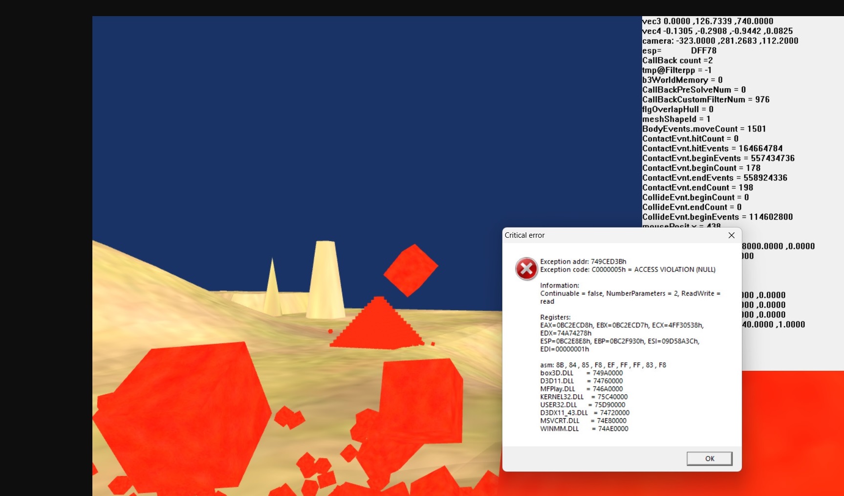
Code: zzCylindrSize dd 2.0,1.0,2.0,6 ;height,ofstY,radius,sides int myVrtxs dd 200 dup(0) ;vertx buffer ;myIndxs dd 0,1,2, 0,2,3, 0,3,4, 0,4,5, 0,5,6 , 0,6,1 ;cap top 6 triangles. Not gen. i am writed ; dd 7,8,9, 7,9,10, 7,10,11, 7,11,12, 7,12,13 , 7,13,8 ;cap bottom 6 triangles myIndxs dd 800 dup(0) mov eax,myVrtxs ;out vertices to eax mov edi,zzCylindrSize call gen@@Cylinder ;gen top cap. All normals = 0,1f,0 ;my vertex stride 32 bytes Pos.xyz,UV.xy,Normal.xyz movss xmm0,[edi] ;get Height addss xmm0,[edi+4] ;Height+ofstY movss [edi+4],xmm0 ;if want change radius bottom cap and get cone ! rept 1 { mov ecx,0.4 movd xmm0,ecx mulss xmm0,[edi+8] movss [edi+8],xmm0 ;radius*0.4 } call gen@@Cylinder ;generated bottom cap. All normals = 0,-1f,0 call Gen@@Tube ;if we want cylinder ;get num vertices sub eax,myVrtxs shr eax,5 ;/32 my stride 32 ;get bytes idices sub edx,myIndxs ;get num idices shr edx,2 ;because one indx=4bytes ;if sides=4 we get boxe ! gen@@Cylinder can get 5 type meshes(boxe,pyramid,cone,cylinder, one cap as flat circle) ;We can generated one cap top and set central point +0,10.0,0 and get cone or pyramid(sides=4) ! I created two caps as cone and get mushroom.
![]() Last edited by Roman on 01 Aug 2026, 13:57; edited 3 times in total |
|||
|
| Goto page 1, 2 Next < Last Thread | Next Thread > |
Forum Rules:
|
Copyright © 1999-2026, Tomasz Grysztar. Also on GitHub, YouTube.
Website powered by rwasa.